Hacking Roku: Part 6
With what is (hopefully) a UART TX pin discovered on the Roku, let’s try using a logic analyzer to confirm it.
Welcome back. In Part 5 of the series I demonstrated using a multimeter to identify ground pins and hunt for signs of UART and other items of interest.
As always, let’s start with a recap of the current state of the test plan. Completed items have been removed to keep it clean. You can always refer back to earlier articles to see those steps.
Roku XD Test Plan
Objectives
- Learn basic hardware hacking tools and techniques
- Dump the device firmware
- Get root on the device
Logic Analyzer Testing
- Confirm possible UART on J10 Pin 6
- Check other pins for anything else interesting
Further Testing
- Analyze firmware files
- Pin Glitch the NAND Flash chip
Based on the chatter that I saw coming out of Pin 6 on header J-10, I am fairly confident that if I just stuck a USB/UART adapter on that I would see something interesting. But if I just went right to that step, then I would not learn how to use my logic analyzer, and my primary objective is learning that kind of thing.
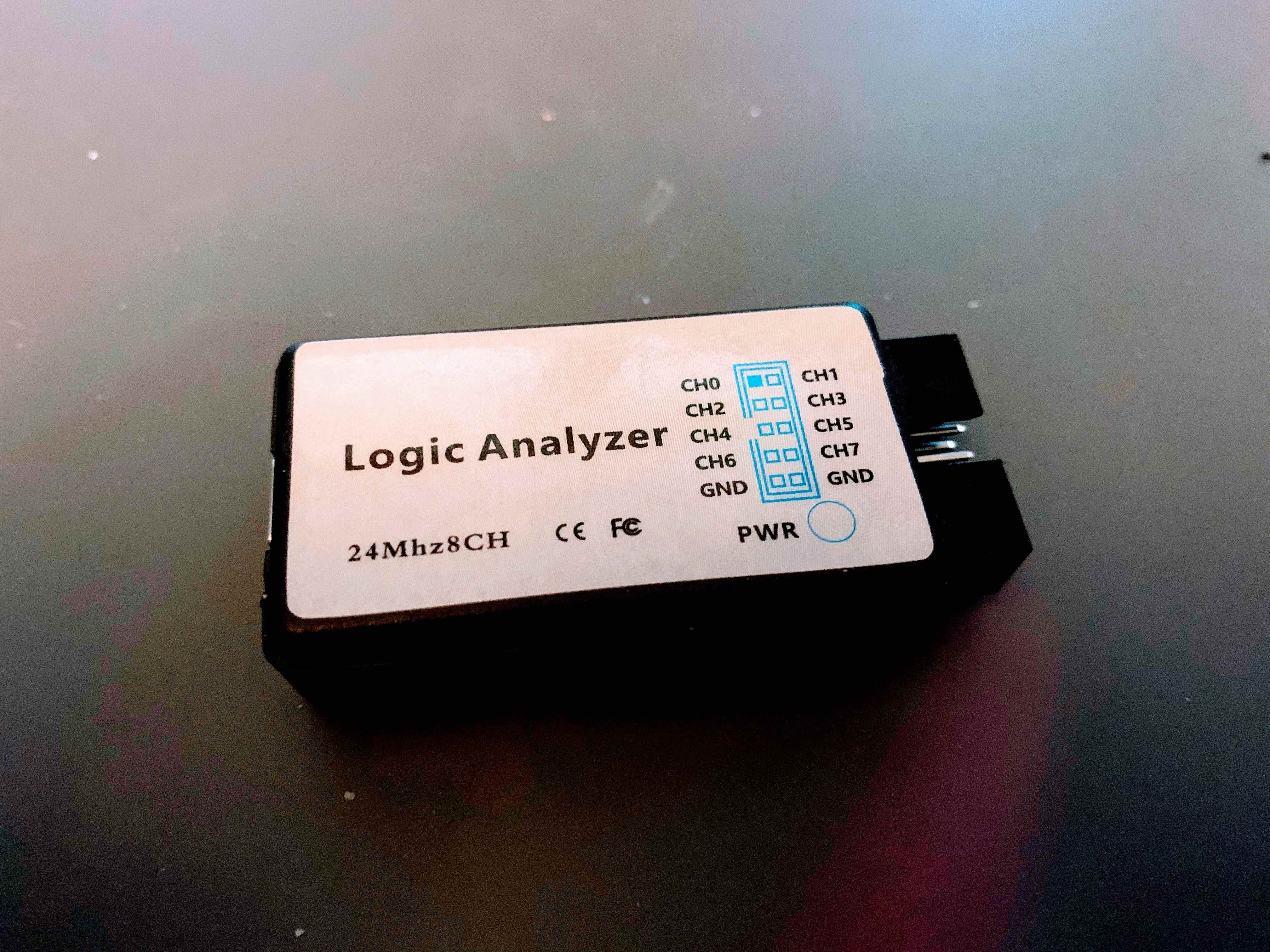
This is the logic analyzer that I have. I think the offical brand name was Hiletgo but there are many, many clones of this product available and they are very inexpensive - around $20 US. Now if you’ve got money to spend, the gold standard for these devices right now come from Saleae. They start at $400 US although they do have a generous discount available for students and hobbyists - at the time of writing they offer the base model to those folks for $200. The Saleae analyzer can accommodate a much higher sampling rate than the cheapo analyzer which can be really helpful. But if you’re just starting out, a cheap one will do you ok for awhile. In addition to a reputable product Saleae offer a really nice software tool for interfacing with USB logic analyzers. It’s not open source, but they currently have it available as an unlimited trial at no cost, and it works just fine with other logic analyzers.
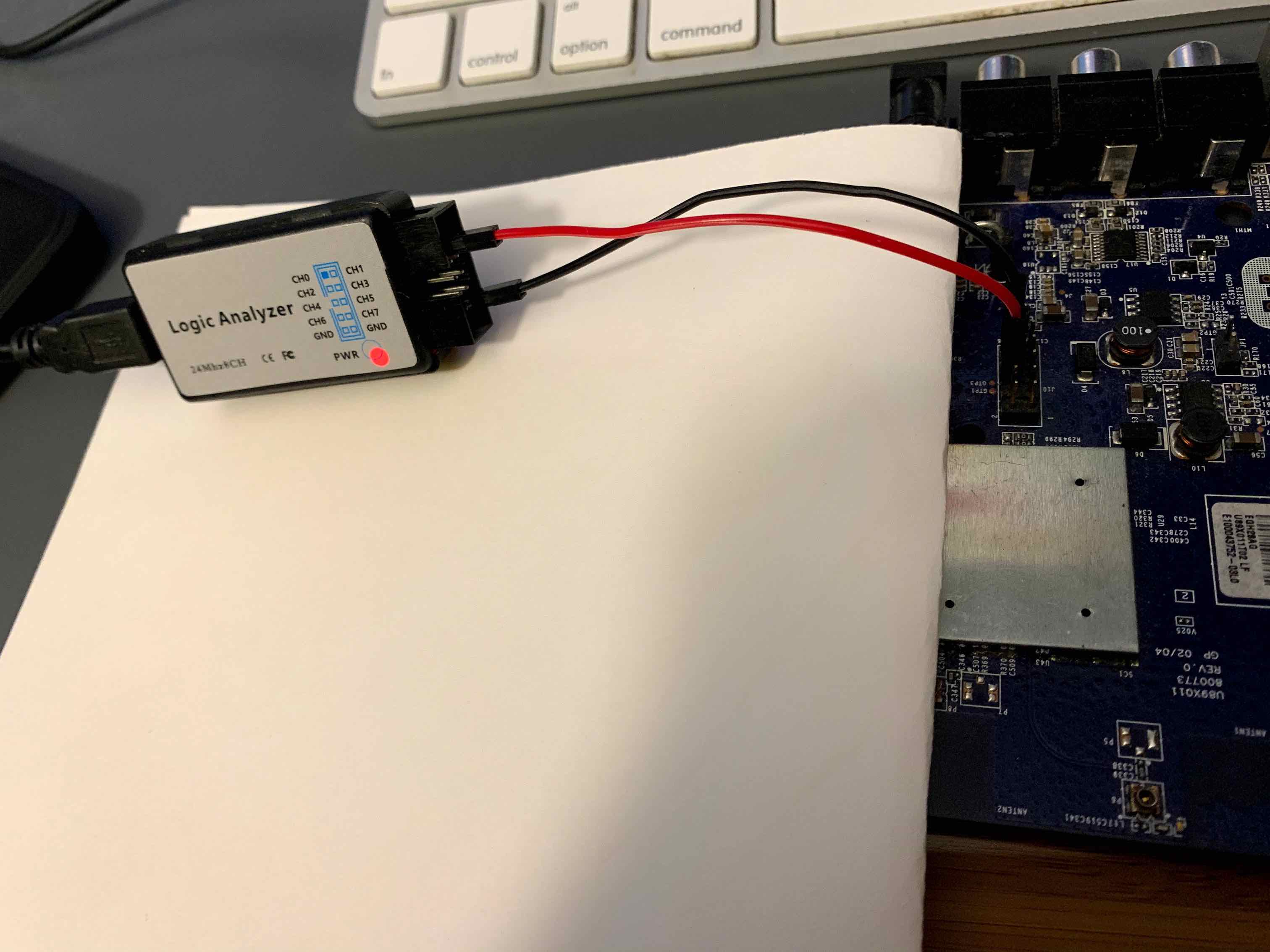
Setting it up is straightforward. It helps to have a some jumper wires with female<->female dupont connectors on them. They are cheap and easy to get online. With the device powered off, just connect the device ground to one of ground pins on the logic analyzer, and then connect each of the pins you want to analyze to one of the channel pins. Plug the other end into a USB on your computer and you’re ready to start analyzing in the software.
The Logic software is fairly intuitive. Since the pin we’re testing hangs around 3.3V and flickers downward, we’re looking at a signal that is held high and is active when low. That means in Logic, it’s necessary to go in the Trigger tab on the right-hand side of the screen and choose Falling Edge for whatever analyzer channel is attached to the pin on the Roku. This tells Logic to start recording from that channel when the signal drops low, which should be when the chatter begins. It will record for as long as the Capture duration after trigger setting specifies, so set that to 45 seconds to catch the whole bootup sequence.
After that, press the “play” button in the upper-right hand corner, switch on the Roku and watch what happens.
If you get a ReadTimeout error, that means the sampling rate is set too high for your logic analyzer. The default is 24Ms/second (24 million samples/second). The real Saleae devices can probably handle this but if you’re using a cheap one like mine, you’ll want to lower that until the error stops.
 Here’s what the output looks like zoomed into a resolution of .1ms … you can see the signal bumping up and down for different durations representing zeros and ones. Cool!
But how do we figure out if this means anything?
The Logic app comes with handy analyzers to simplify this. Choose the Analyzers icon on the right-hand toolbar and then click Async Serial. For most settings the default will suffice but we’ll need to guess at the bit rate. There are relatively few choices and some are more common than others. 9600 and 115200 are two good guesses to start. If you see nothing or the output looks like nonsense, or you see a lot of framing in the error column try a different bit rate.
I’ll try 115200 first.
Looks like I am on the right track. Logic is seeing data but it’s showing me in binary. If I hover the mouse pointer over Async Serial a 3-dot options menu appears. I select ASCII in there and I can make out text in the table. If I zoom out on the wave form a little bit, Logic superimposes the ASCII characters above where they appear.
I can make out Griffin Primary Bootloader! This is definitely a UART output! Going back to the Analyzers pane, if I click on the little Terminal icon it displays all of the output in an easily readible terminal-like format. Here’s what it says, in part:
--------------------------------------------------------------------
-- Griffin Primary Bootloader 0.1-4674, NI (05:12:10, May 21 2009)
-- Andre McCurdy, NXP Semiconductors
--------------------------------------------------------------------
Device: PNX8935 M1
Secure boot: enabled, keysel: 13, vid: 6 (expecting 6)
Poly10: 0x0000003F
Flash config: 7 (omni: 8bit NAND), timing: 0x04
CPU clock: 320 MHz
DRAM: 197 MHz, 2 x 2 64MByte 8bit devices: 256 MBytes
NAND: Samsung SLC, pagesize 512, blocksize 16k, 64 MBytes
NAND 0x00004000: valid header
NAND 0x00004000: valid image
aboot exec time: 146146 uSec


U-Boot 1.2.0 (NAND or Rescue image - so no hardware configuration) (Sep  1 2010 - 16:28:09)

CPU is PNX8935 M1, CPU speed 320 MHz
Secure boot: enabled
Flash type is Nand
DRAM:  256 MB
## Unknown FLASH on Bank 1 - Size = 0x00000000 = 0 MB
Flash:  0 kB
NAND:  Remapping Bad Blocks:
64 MiB
Env: default
Splash:  done
u-boot startup time so far: 1078 msec
There is a lot of great information here. Now that I know I have found a UART, I’m going add some more items to my test plan:
UART Testing
- Connect USB/UART adapter to UART
- Identify RX pin
- Interact with the device
If all goes according to plan, I’ll use trial and error (and some educated guessing) to figure out which pin on the board is the RX pin that I can use to type commands to the device. If I’m lucky, I might even find a root shell waiting for me!
But before I jump into that, as long as I’ve got the logic analyzer out and set up, I decide to test the other pins on the board. Long story short, I did not see anything of obvious value, but I did have a crazy idea while I was doing this…
I wonder if I can hook the logic analyzer to the legs of the iR receiver and see what it looks like when it receives a signal from the remote…could I maybe reverse engineer the remote protocol and the fuzz the iR receiver? Could that essentially be an unrestricted input that I can abuse?
I’m going to add that under Further Testing.
Here’s what the plan looks like now:
Roku XD Test Plan
Objectives
- Learn basic hardware hacking tools and techniques
- Dump the device firmware
- Get root on the device
Logic Analyzer Testing
- Confirm possible UART on J10 Pin 6
- Check other pins for anything else interesting
UART Testing
- Connect USB/UART adapter to UART
- Identify RX pin
- Interact with the device
Further Testing
- Analyze firmware files
- Pin Glitch the NAND Flash chip
- Check iR receiver with Logic Analyzer
In the next part, we’ll have a look at how to use the USB/UART adapter to interact with the serial interface.


