Fix.
Learn.
How To: Program An ATmega328P with Tigard and avrdude
Last month I got a #badgelife badge at a local hacker convention. In addition to soldering it, it had to be programmed. This is the first badge I’ve encountered that did not have a USB interface, so I had to learn how to program it using a programmer. In case you ever need to do something similar yourself, here’s a way you can do it with a Tigard.
WOPR
WOPR Summit is a fledgling hacker convention based in the Philadelphia area. The first WOPR Summit was held in 2019 in Atlantic City. While they had planned to have another con in 2020, the global pandemic prevented them from hosting further events for awhile, so they did not convene again until 2021 when they hosted a small meetup. This year, they hosted a full 2-day convention at Temple University. It was really fun to experience something that is sort of the opposite of DEF CON - small, intimate, single track, much easier to meet and talk to people.
Of course it wouldn’t be a hacker con without a badge, and if you’ve been following me here or on Twitter for more than a minute, you’re probably aware of my love of all things #badgelife so of course I bought one of the badges. True to form, it looks like the WOPR from War Games.
![]()
The badge came partially assembled with the Atmel ATmega328P MCU and most of the surface mount (SMD) components already attached. I had to solder on a crystal, a couple of SMD shifters, an SMD resistor, the battery clip and 3 sets of 16-segment displays.
As an added challenge, the badge did not come pre-programmed AND it does not have a USB interface. Previous badges and other similar devices I’ve played with in the past have had some kind of USB interface on them which makes it easy to interact with using the Arduino IDE. Just plug it in, configure some settings and you can upload code easy-peasy.
With this badge, you instead have to use an In-System Programming (ISP) header on the target board (the badge, in this case) and an intermediary device such as ISP Programmer to act as the interface between your computer and the badge.
ISP without an ISP Programmer
The con organizers suggested an ISP programmer available on Amazon and it was only $10 but before I pulled the trigger on buying it, I started to think maybe I already have something I can use. Over the past few years I’ve acquired a decent collection of gadgets for this kind of thing.
I’ve got ESP32s and ESP8266s.
I’ve got USB/UART interfaces.
I’ve got an Adafruit Metro which is an Arduino clone.
I have a couple of old Teensy 2.0s.
I’ve got a BusPirate, a Shikra, a Tigard.
Surely I can do this with the tools I already have on hand, can’t I?
So, I started doing some digging. The first thing I figured out is that you can use an Arduino as an ISP. So I should be able to do this with that Adafruit Metro. It seems a little bit complicated. There is also some concern about components on the badge not being 5v tolerant and because this badge was designed a couple of years ago the designers’ memories are a little fuzzy. The Metro can actually be converted to 3v3 by cutting trace and soldering two pads, though, so it should be fine either way. I started to read up on this some more when I happened to notice on the first image in this article that one of the programmers available in the Arduino IDE is BusPirate as ISP. I have a BusPirate! Let’s see how that looks.
A quick search revealed a pretty decent explainer straight from the designers at Dangerous Prototypes on using the BP as an ISP. Nonetheless I was still a little hesitant to use the BP for a few reasons. One is that I couldn’t remember how to power the target device from the BP with the correct voltage. Another is that I found the chart describing the wiring hard to follow. Looking back at it again now as I write this post I see how the wiring should go but when I read it a few days ago for the first time I was unsure. Last, I just don’t love using the BP. It can be slow, and having to interact with it via serial connection is a little odd. It was 10+ year old tech when I bought it in 2020 and newer devices are much faster and easier to use. Also I pre-ordered a Tigard and I’ve had it for awhile now and I’ve only used it a couple of times…and if a BP can be used as an ISP programmer … maybe the Tigard can as well?
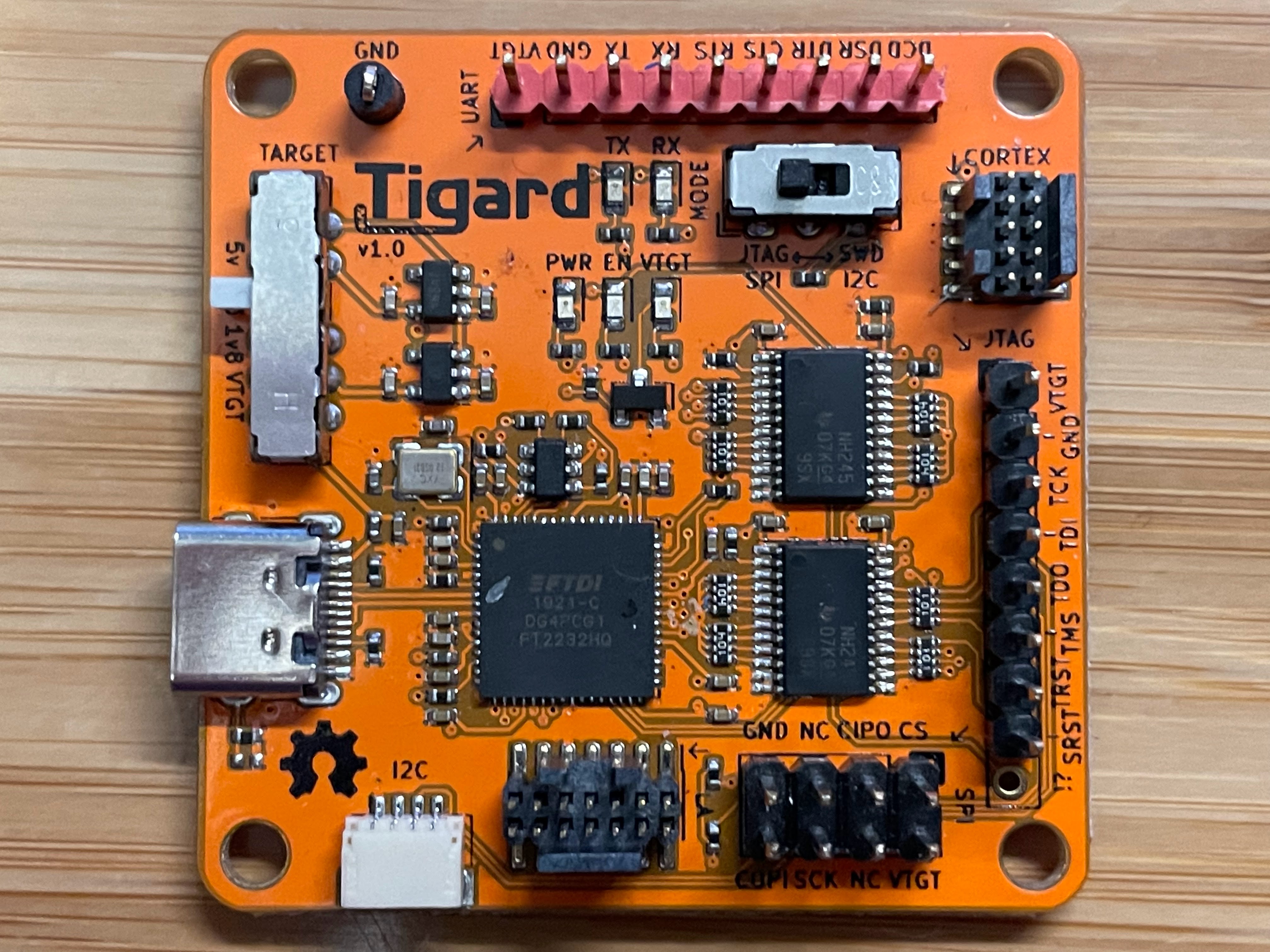
Another quick search revealed that the answer is definitely yes. But this article is a bit vague on details - it explains how to get avrdude (more on this in a moment) to work with Tigard, but not much on wiring it up or actually using it. A bit more research revealed the wiring arrangement and this chart is much easier to understand than the one for the BusPirate. Still a bit more research gave me a nice pinout graphic of the ISP header on the badge. The last piece of the puzzle was the necessary avrdude commands. avrdude is a command line utility that allows reading/writing of AVR microcontrollers, including the ATmega328P on the WOPR Summit badge. The same article on Sparkfun also has a pretty good primer on using avrdude.
Tigard + avrdude
Now to put everything together.
First, I needed the code in the correct format. The con organizers provided source code in .ino format, which is plaintext C source code. avrdude requires the compiled bytecode in .hex format.
To get the compiled bytecode, simply open the .ino file in Arduino IDE and choose Sketch -> Export Compiled Binary. The .hex files will appear in the same folder that the .ino sketch was in.
Note: If your project requires a bootloader it is important to choose the correct target board because it influences what bootloader is exported. In my case I chose Arduino Uno as the target board because this also uses an ATmega328p. This gave me two .hex files, one with and one without a bootloader. I will need the one with the bootloader.
Next I had to wire it up. It’s preferable to NOT solder a header on for this type of thing because typically once the board is programmed it rarely needs to be done again. An adapter with pogo pins is a good way to do this but I don’t have anything like that. I also don’t have any sets of 2x3 pin headers at the moment. But I do have a spare male SAO header that fits the holes on the board.
I wired this up according to the diagrams I found using Tigard’s JTAG tail, making sure to remember which pin I used as pin #1 (I arranged it so that the notch on the SAO header would be along the edge of the board).
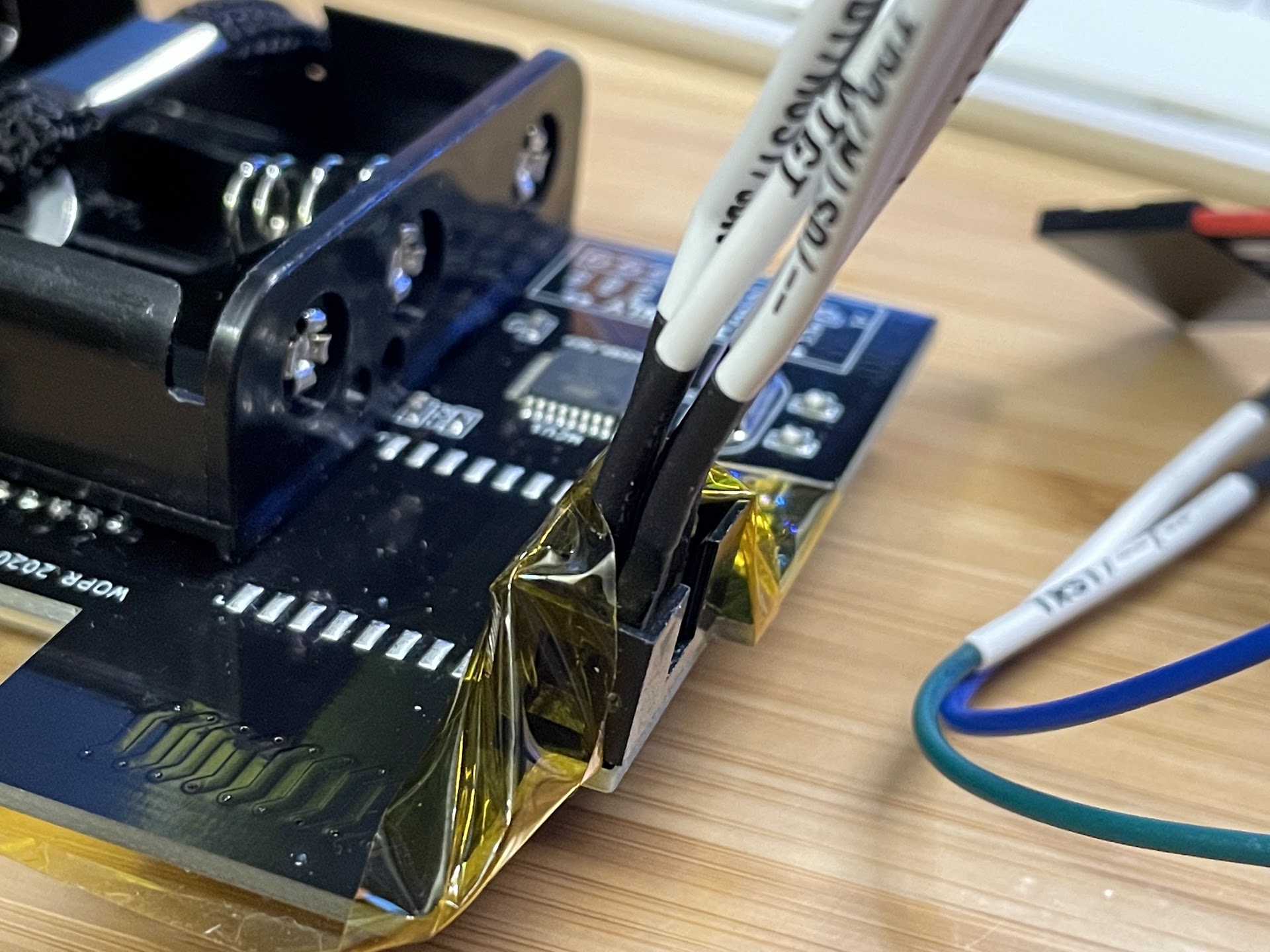
Then I inserted the wired-up SAO header into the holes on the board and used a piece of kapton tape to hold it in at an angle to ensure that the pins all make some contact with the board’s conductors.
It’s a little dodgy - it works best if I apply some manual pressure with my finger when I am actually reading/writing to the MCU. Even with this, I had some corruption on a few tries and had to re-do the upload. Finally, I plugged the other end of the tail into the Tigard’s JTAG header, making sure to get the orientation correct.
On the Tigard I then set the mode switch to JTAG/SPI as directed in the documentation, and set the voltage selector to 3v3. I connected the Tigard to my computer using USB-C.

Now I just needed to use avrdude to write the firmware. Before you can use avrdude with the Tigard be sure to grab the tigard.conf content from either the Tigard github or the securinghardware.com link above and save it locally.
One last gotcha is that the completely blank MCU had no fuses set. Fuses are bits that can be toggled to configure the MCU in various ways. There is a pretty good explainer here and a handy fuse calculator is available as well. Most importantly for me, the fuses need to account for the external 16MHz crystal used for timing and the presence of the bootloader. Through some experimentation I determined that the following fuses worked: Low 0xFF, High 0xDA, Extended 0x05.
So my avrdude command ends up looking like this to set the fuses:
avrdude -C +tigard.conf -c tigard -p atmega328p -U lfuse:w:0xFF:m -U hfuse:w:0xDA:m -U efuse:w:0x05:m
Followed by this to upload the bootloader and application code:
avrdude -C +tigard.conf -c tigard -p atmega328p -U flash:w:WOPR_0x01.ino.with_bootloader.standard.hex
It’s possible to combine these into a single command as well.
TL;DR
In a nutshell, the steps for flashing an ATmega328P (or other avr-based board) using avrdude and a Tigard as an ISP are:
- Set correct target board in Arduino IDE
- Export compiled code from Arduino
- Wire Tigard JTAG header to target board’s ISP header according to the diagrams
- Select JTAG on Tigard mode switch
- Select desired voltage on Tigard
- Plug in Tigard via USB-C
- Set fuses -
avrdude -C +tigard.conf -c tigard -p atmega328p -U lfuse:w:0xFF:m -U hfuse:w:0xDA:m -U efuse:w:0x05:m-> Note different fuses may be needed depending on device config - Upload code -
avrdude -C +tigard.conf -c tigard -p atmega328p -U flash:w:/path/to/firmware.ino.with_bootloader.standard.hex
HACK THE PLANET WOPR
Of course in the spirit of hacking I had to at least tweak the code a little bit by having the badge show T.FISH where it previously displayed SPEAKER.
Bonus - Using Tigard as programmer directly via Arduino IDE
It would be a little more convenient if I could upload code via that Tigard from within Arduino IDE since I already have to use Arduino IDE to compile the code. I’m sure there is some way to compile the code via command line but I don’t know it yet.
According to this article it is possible to list Tigard as a programmer in Arduino IDE by editing the programmers.txt config file.
On my Mac this file was in:
/Applications/Arduino.app/Contents/Java/hardware/arduino/avr
But after upgrading AVR via Arduino’s Boards Manager it started using ~/Library/Arduino15/packages/arduino/hardware/avr/1.8.6. You might have to do some hunting on your own system.
Once you’ve located programmers.txt make a backup copy and then add the following to the end of it:
tigard.name=Tigard as ISP
tigard.communication=usb
tigard.protocol=tigard
tigard.program.tool=avrdude
tigard.program.extra_params=-Pusb
tigard.program.extra_params="-C+/path/to/tigard.conf"
There is one other gotcha, though. For some reason the version of avrdude included with the AVR core package in Arduino is a little old and does not have some of the necessary compile-time options enabled.
- Pro tip: To troubleshoot
avrdudeissues in Arduino, go into the preferences and tick the box forShow Verbose Output during: Upload
If you see this error you need to use a different version of avrdude:
avrdude: Error: no libftdi or libusb support. Install libftdi1/libusb-1.0 or libftdi/libusb and run configure/make again.
On my Mac I had already installed avrdude 7.0 via homebrew.
To tell Arduino IDE to use that version of avrdude, find the platform.txt file which should live in the same location as programmers.txt. Again, make a backup copy in case you make a mistake.
Find the line tools.avrdude.path={runtime.tools.avrdude.path} and comment it out with a # at the beginning of the line.
Then immediately below it, add: tools.avrdude.path=/usr/local.
Note: if your avrdude is installed somewhere else you may need to specify a different path.
Note also that the two lines immediately following tools.avrdude.path are based on this value, so if your avrdude executable is not in /usr/local/bin and/or your avrdude.conf is not in /usr/local/etc then you may need to manually set these paths.
Once you’ve got everything set up, restart Arduino IDE. If you go into Tools -> Programmer, you should now see Tigard as ISP as an option. Select it.
Now, wire everything up and go to Sketch -> Upload Using Programmer.
If you did everything correctly, Arduino will compile the code and then use avrdude to upload it to the target board just as we did from the command line before.
One final word of warning - it’s possible that there are compatibility issues with avrdude 7.0 elsewhere within Arduino IDE so keep that in mind…if you see weird errors you may have to switch back to the original avrdude settings in platform.txt.
Bonus 2 - Using Tigard to program the bootloader directly via Arduino IDE
It’s also possible to use Tigard to program the bootloader, but it’s a little more complicated because Arduino will write the fuses AND upload the bootloader. In order to get Arduino to write the correct fuses you must either find an existing board that Arduino knows about that uses the same fuses, or you have to add a custom board specification. This is all done in boards.txt which lives in the place as platform.txt and programmers.txt.
For example you could find the Arduino Uno block in there and add a copy of the Arduino Uno block and customize it with a different name and the fuses from above. I believe it is also possible to specify one-off boards and programmers by placing boards.txt and programmers.txt in a predefined subfolder in the sketch folder as well. These will only be available when that particular sketch is loaded.
Once it’s all configured and you have restarted Arduino, select the new board you added in Tools -> Board -> Arduino AVR Boards and select the Tigard as ISP programmer. Then choose Tools -> Burn Bootloader and it should do its thing.
I did not actually try this because most of the time you only need to write the bootloader and fuses once so it’s a lot of fuss without much reward. As I already have a working badge and am able to reprogram it from within Arduino IDE, I did not spend additional time testing this out but it should work if you’re so inclined.