Fix.
Learn.
Xiegu G90: Now With More Mic Hook
After my success printing up a clip-on speaker redirector for my Xiegu G90, now it’s time to figure out a hook for the microphone.
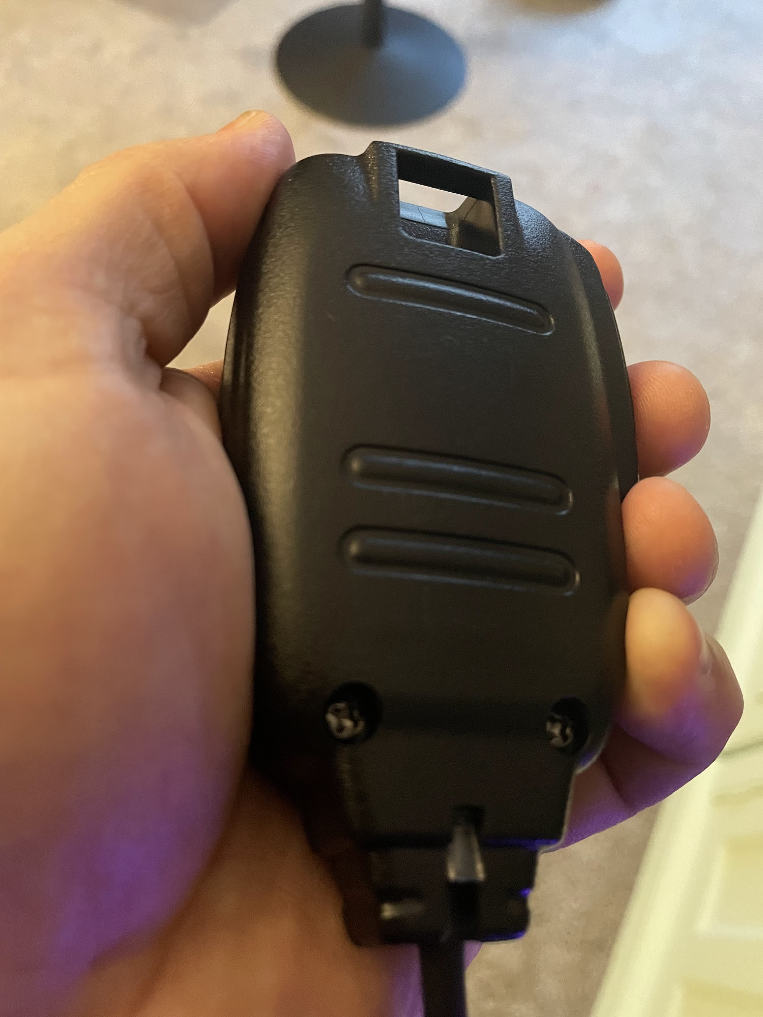
In my last blog post I wrote about a few quality-of-life annoyances that I had discovered with the G90 and how I managed to fix two of them with 3D printing. I had not yet sorted out the microphone issue. When I first used the radio, I quickly found that the microphone could be kind of unruly between its own weight and the weight of the coiled cord. It always felt like it was getting in the way of itself, or sliding off the table if it got too close to the edge. Trying to juggle the microphone while operating the radio controls, using a computer to check POTA/SOTA spots, and either using pencil and paper or the computer to log was a little unpleasant. Like most radio mics, there is a loop molded into the G90 mic so that you can hang it from a hook, I just needed a hook to hang it from. Also, the temperatures have continued to hang in the Fahrenheit teens and below and the now-frozen snow covering the ground is not going anywhere soon so I am still off the air for awhile. I might as well keep “playing radio” by doing other radio-adjacent things!
It seems silly to design something that someone has already done well enough (unless maybe you really just want to try your hand at it?), so I started with a quick search of Printables and Thingiverse. I was surprised that across both sites I only found two options. One was a hook designed to be attached to a desk, which is not what I need for my mobile setup. The only other option was only available as a Fusion file, with no STL file to send to a slicer to print. I could, of course, download Fusion to open the file and export it, but I am trying to stick to FreeCAD. From the photo, it looks like a simple design: a small hook that clips over top of one of the grab loops attached to the front of the radio. My original plan was to make my own version of this. The simplicity of the design seemed perfect for my skill level.
But as I started looking at the radio and the mic, I realized I did not like this design very much, for two reasons. One is that the loop on the mic is at the very top of it, so the entire mic hangs down below the level of the hook. You can see from the pic on Thingiverse that the mic hangs very low from that clip and the front of the radio has to be elevated quite a bit, otherwise the bottom of the mic or the cable will push against the table and interfere with the mic hanging securely. The second is that the mic faces sideways. That’s mostly an aesthetic issue, and maybe it’s even preferable from a usability standpoint because if you pick up the mic from this position, your thumb would be right on the PTT key, ready to use. But, I just thought it would look nicer to have the mic facing the front. I quickly decided that I wanted a drastically different design.
As with the speaker redirector and stand that I had already printed, I liked the idea of something that I could easily put on and remove as needed. And then, while I was holding the microphone in different places around the radio to try to envision how this thing should look, suddenly I had an idea: I could use the same clip-on mount that I had used for the speaker redirector and modify it so that it would support a microphone hook instead! I took a few measurements and got to work in FreeCAD. It was going to be a lot taller than I imagined in order to keep the entire mic and the end of the cable from hitting the surface even when sitting flat on a table, but a great thing about 3D printing is that if you do the design work correctly, you can easily adjust and make changes if your printed part doesn’t work exactly the way you imagined.
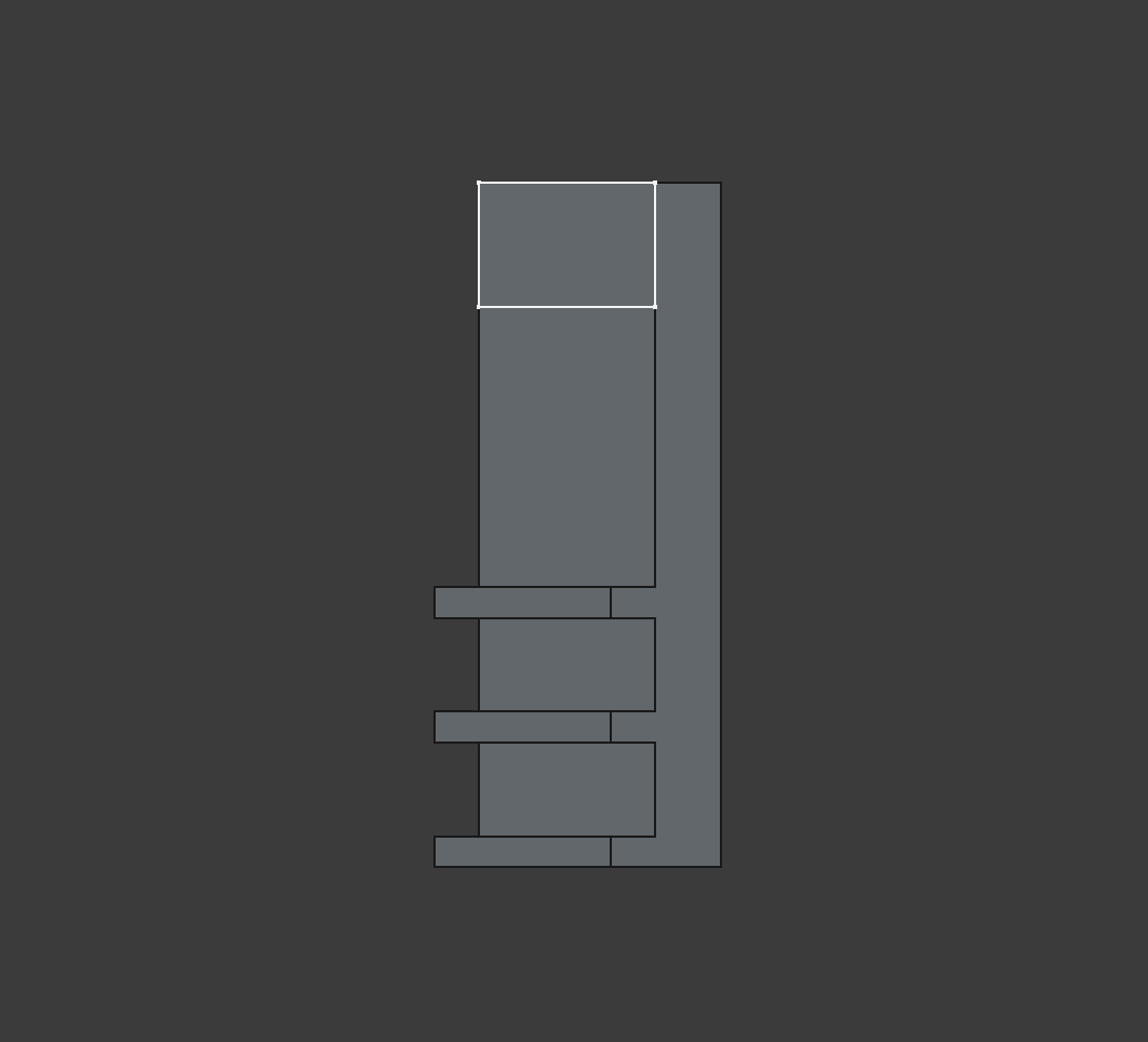
When I made the clip for the speaker redirector, I stopped and saved a copy of the early part; the part with the teeth that engaged the cooling fins. I just had a feeling that it would be good to have in case I wanted to design something else that clipped on in the same way. Since the bar across the top of the radio would be continuous for this part, I just needed to create that bar, plus the other toothed clip. FreeCAD’s Part Design Workbench has a mirror tool. So I simply padded out the bar to half the needed distance and then used the mirror tool, and then I was left with a continuous bar that would clip across the radio, and a perfect mirror image of the clip on the other end. I probably should have printed this at a reduced thickness just to be sure of the fit, but because the width measurement between this part and the speaker redirector were exactly the same I was pretty confident it would fit fine.
I also realized that this might have been the better way to design the speaker redirector - I could have made this continous clip, placed the quarter-sphere of the redirector in place along the spine of the clip and then used the pocket tool to remove the part of the spine inside the quarter-sphere. This would have left me with a single continuous solid instead of having to use the trick of sticking them together in FreeCAD and then exporting the two parts to STL. I may go back and try setting it up this way in FreeCAD at some point. It’s not a huge deal, but in its current form it’s not truly parametric; if I ever want to modify the design I will likely have to change measurements in one or more sketches instead of just tweaking some numbers in the parameter spreadsheet.
Back to the microphone hook, though. Another thing my expert 3D printing friend told me long ago was this: when you’re designing a part to be 3D printed, you always have to think about the constraints of 3D printing, namely that you can’t print in empty space. Everything that you print has to either print directly onto the print bed or a previous layer, or it has to have printed supports. Now, these days printed supports are not nearly as troublesome as they used to be. The slicers have better support options that are easier to remove and don’t make nearly as much of a mess. If you have a printer that can handle multiple filaments, you can print the body in one material (e.g. PETG) and print supports in a different material like PLA and you will have a support structure that is not bonded to the main part and is easy to remove with minimal residue. But, I do not have one of those printers and I prefer parts that do not require supports where ever possible.
So I had two design considerations - the boom that will come up vertically out of the spine, and the hook itself. The clip part must be printed on its back or front side; no other orientation would be possible. So, anything based on this clip must to be designed to print in this same orientation.
The boom needed to be at least 12mm wide to accommodate the full width of the loop on the microphone. But it probably did not need to be the full 8mm depth of the spine. I guessed that half the depth (4mm) would be more than sturdy enough to support the weight of the mic and cable. No need to waste time and material making it stouter than necessary. Visually, I would be inclined to center the boom on the spine, but then it would not be flat to the bed when printing. One side of the boom would have to be flush with whatever side of the spine was on the bed. Also since I wanted the hook facing forward, there would be no way to print with the front side facing the bed. So the nature of “additive manufacture” meant that I would have to print the part on its back, with the boom flush with the back edge and hook coming out from there.
As for the hook itself, if it could be printed sideways then it could be shaped in any way. But since it had to grow vertically out of the boom it would have to accommodate the limitations of the medium. Based on knowledge from my friend and some research online, it seems that most printers can safely print overhangs up to around 50 degrees. At this angle there is enough overlap between the current layer and the previous layer that it will build up securely, with no support structure needed.
So, I made a small block that came straight out of the boom, around the same thickness as the hasp of the mic’s loop. This is the part that the mic would rest on. Then I wanted a bit to stick out at 40-50 degrees with respect to the horizontal printing plane. This would be the lip of the hook that would guide the mic down onto the resting surface and help ensure that it would not fall off too easily. I made an educated guess at how long this piece would need to be at 8mm, and sketched it 8mm below the top of the boom.
Getting the sketch to extrude on an angle was not as straightforward as I would have thought. I looked up a few tutorials and most seemed to suggest adding a line or plane along the sketch at the desired angle and then use the padding tool’s option to extrude along that. But FreeCAD also has an option when padding a sketch to choose a custom direction that takes a vector. This seemed to do what I wanted although it was not exactly clear to me how the vector value relates to the angle. I experimented with vector values along the y-axis until it looked about right.
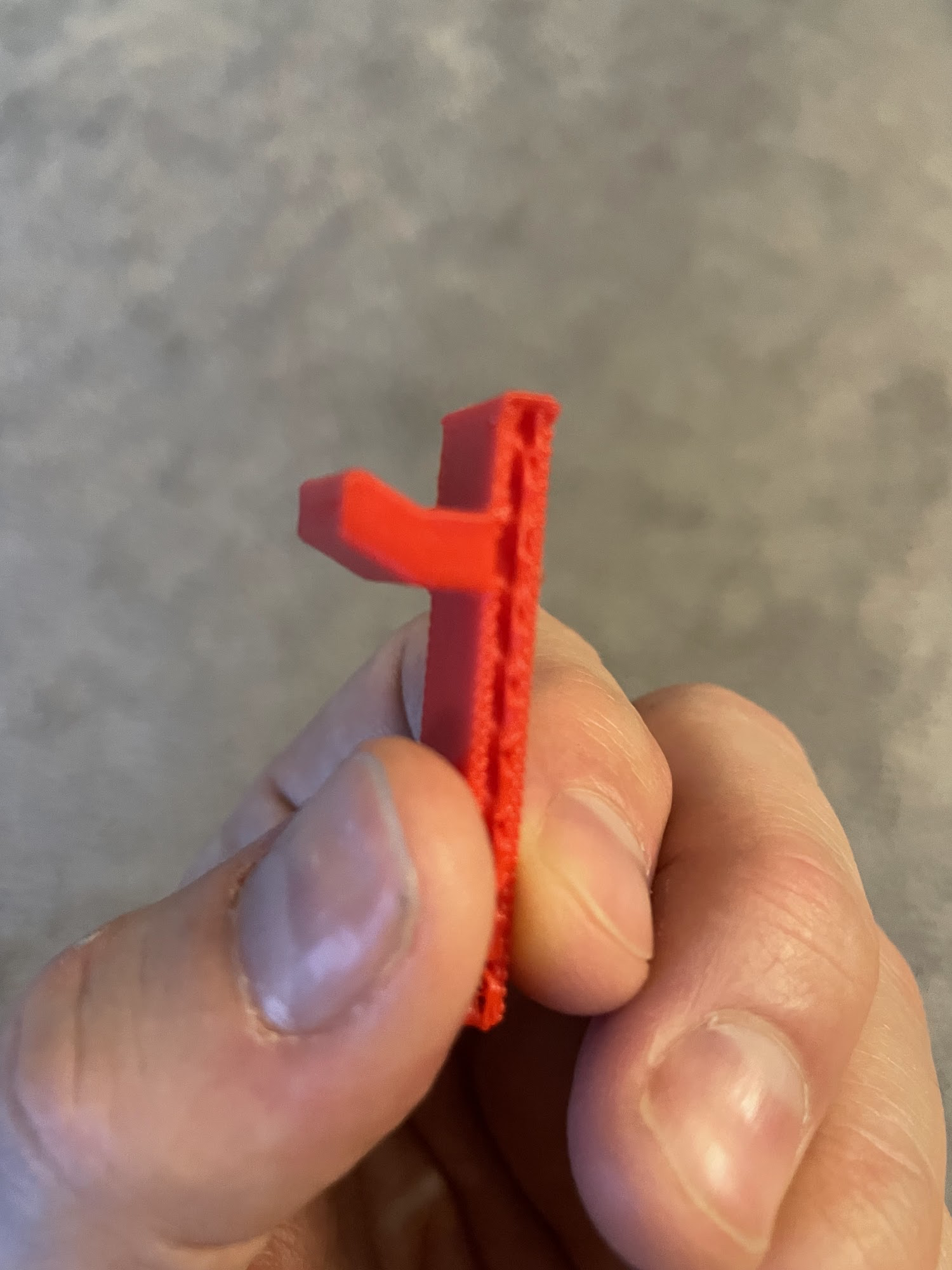
Now, this was a spot where I definitely wanted to do a test print of the hook to make sure it would work. I could not scale the whole thing down or print it thinner because I needed to see not only if it printed successfully without support, but also how the hook worked with the real, full-sized microphone. If you want something at a higher layer, you can actually adjust the Z offset in the slicer so that the parts you don’t want to print are below the plane of the print bed, but in this case I needed the boom and the hook. I use a program called Octoprint to manage my 3D Printer and one thing Octoprint offers is ‘Exclusion Zones’. You can load a GCode file into Octoprint and then draw exclusion zones around parts that you do not want printed and Octoprint automagically figures out how to adjust the GCode on the fly. This is pretty great if you’ve got multiple parts in a GCode file and do not want to print all of them. You can even set up an exclusion zone mid-print so if you have multiple parts and one of them comes un-stuck from the bed and fails, you can put the failed part in an exclusion zone and you might be able to rescue the rest of the print.
In my case, I set up an exclusion zone so that only the top of the boom and the hook would print. It came out a little bit janky but it was a good enough mockup for me to see that … it was not quite correct! The angle was way shallower than I thought it was and the microphone did not seem like it would sit securely on the hook. It felt like a gentle tug or bump would knock it right off. This was going to need some rework. I still felt like the ‘custom direction’ padding was a decent solution, I just needed some way to figure out that whatever vector value I chose gave me the desired angle.
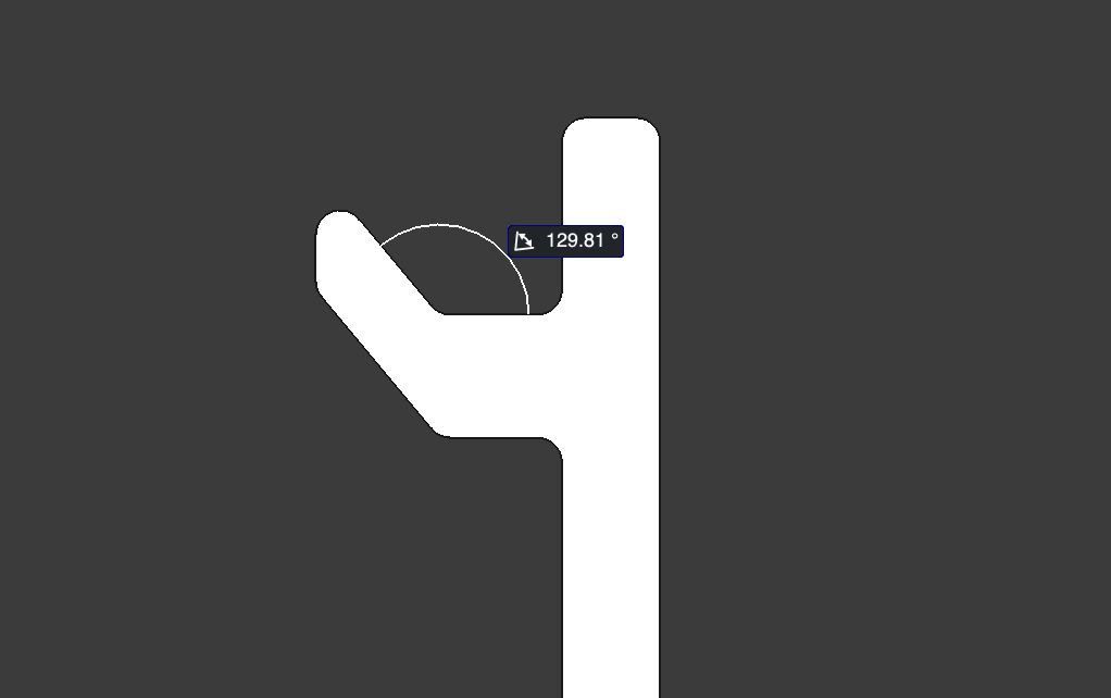 FreeCAD has some built-in tools that allow you to see various measurements of your parts, including lengths and even angles between two faces. In fact, you can even measure something and make that measurement persistent and the displayed measurement will update as you make changes to what are being measured. Perfect! I used the measurement tool to measure the angle between the flat mic rest and the lip. Now remember the angle needed to be 50 degrees or less with respect to the horizontal plane, which in the picture is actually the vertical plane. So, I would a have to subtract 90 degrees from the measurement. I could have added a datum plane parallel to the boom and measured against that to get the ‘true’ measurement but it was easy enough to do the math. After some experimentation I found that a vector of -1.2 resulted in an angle of just about 130 degrees which would give me 40 degrees of overhang which should be easy to print with 10 degrees to spare before it started to hit the overhang limit. I wanted to walk the line of the angle being sharp enough to hold the mic securely in place but not so sharp that it made it tricky to get the mic on and off the hook.
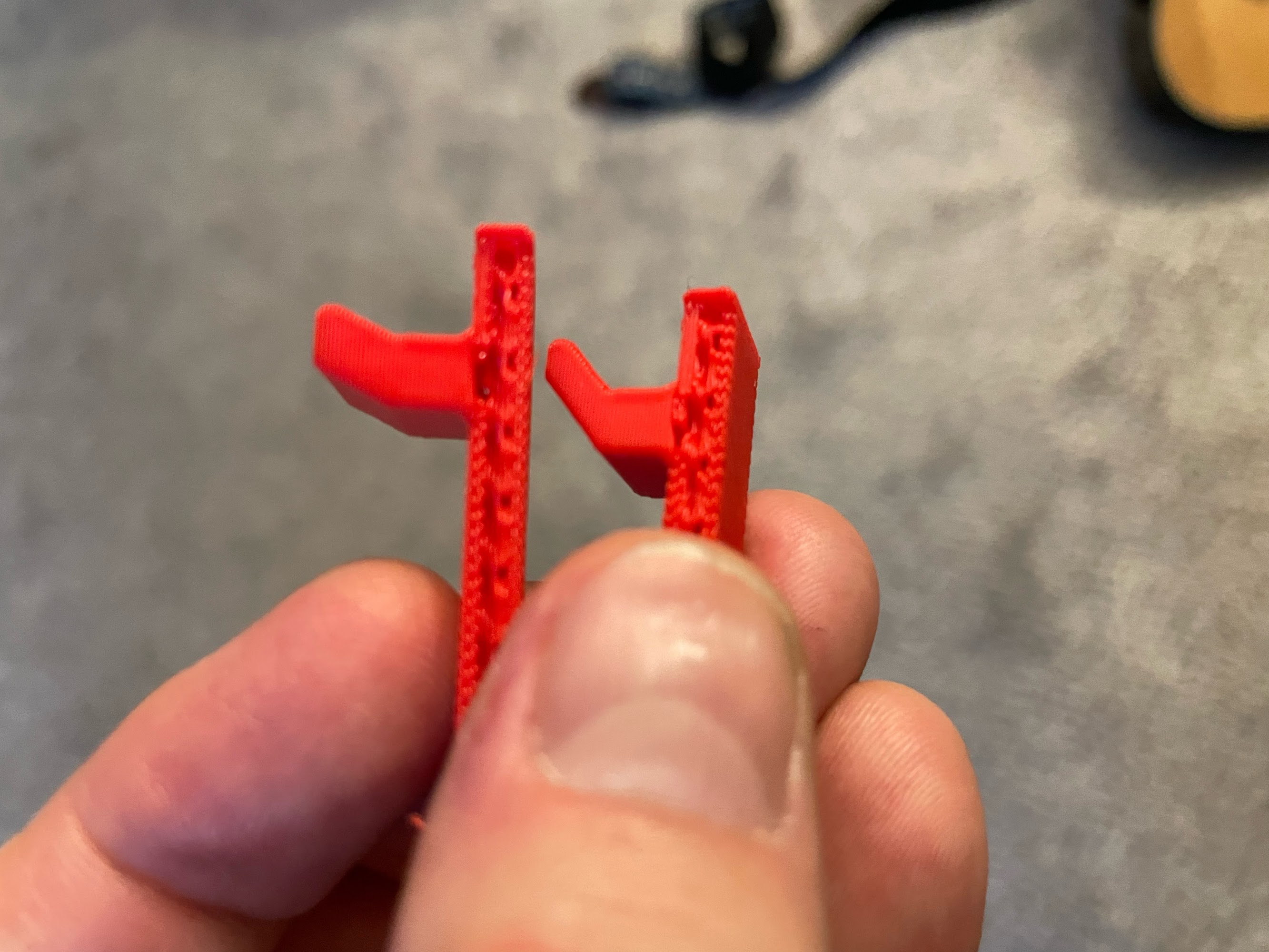
I ran a test print of this updated hook. It printed great! One side effect of padding the hook on an angle was that a sharper angle resulted in a longer lip, so not only did the angle increase but the lip itself was now longer and seemed to ‘grab’ the mic’s loop more easily when hanging it. It also seemed quite secure; I could move the hook around with the mic on it without the mic falling off.
The last thing to do was some cosmetic finishing touches. I added filets to some of the edges to make them a little less sharp and severe. There was only one thing left to do - send the finished part to the printer!
Y’all it came out even better than I imagined! The mic drops onto the hook effortlessly. Once it’s on there it stays on there securely. When you want to pick it up, you just lift it up and it comes right off without sticking or catching. And most importantly, you can easily put it on or remove it as-needed. While it was not one of my design considerations and I haven’t tried it, I think the position of the mic hanging on the hook might work pretty well if you want to use VOX mode, too.
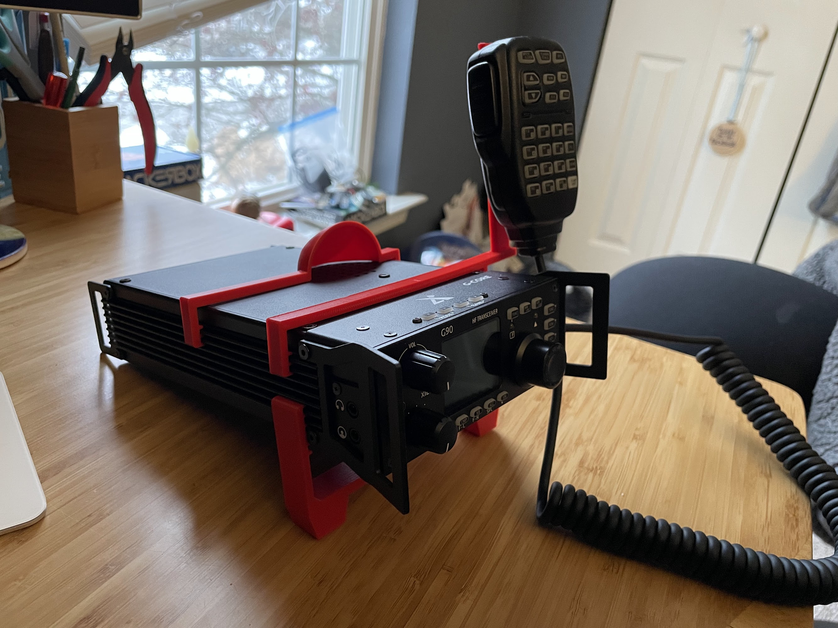
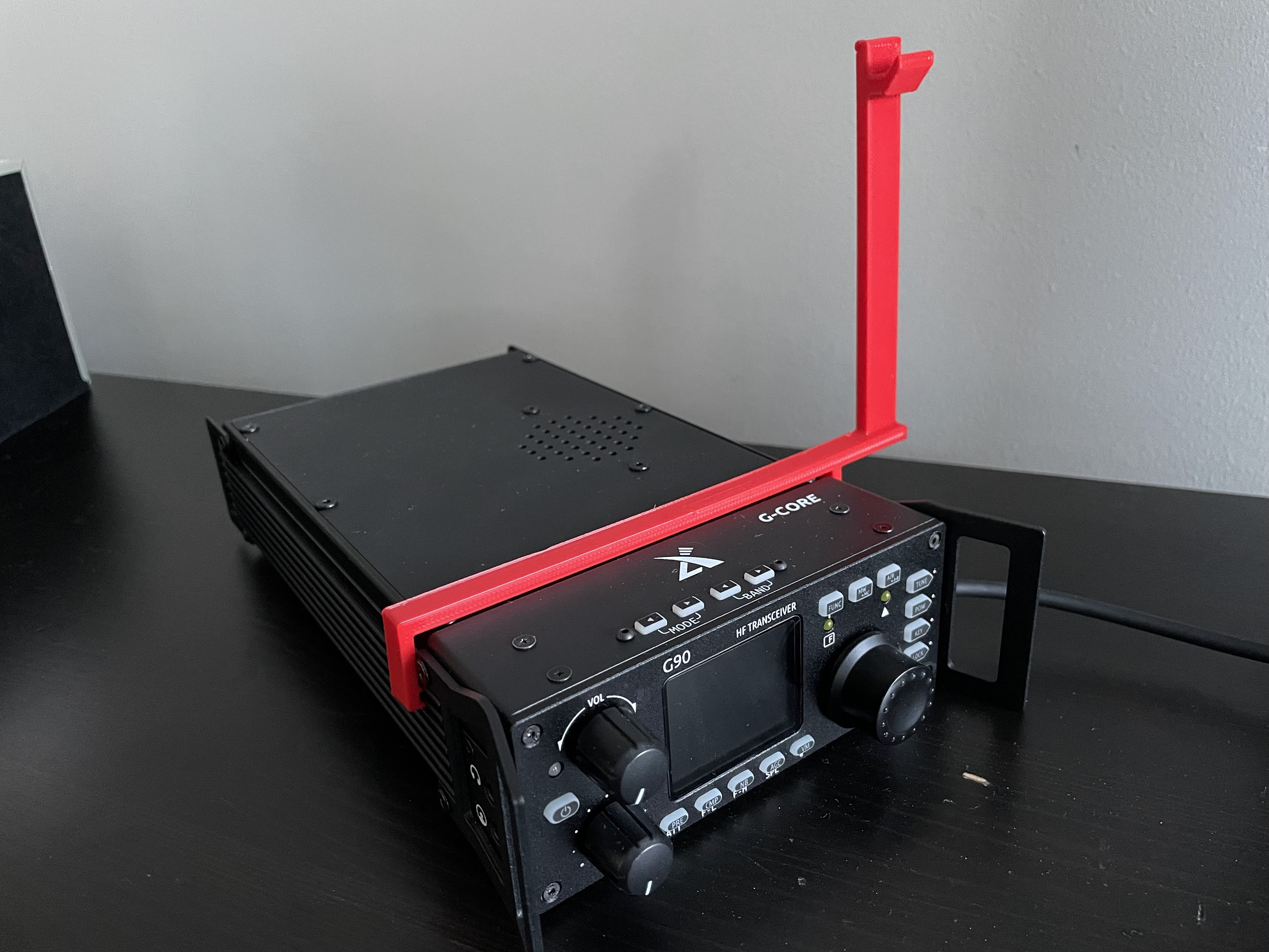
Here is what the radio looks like with the stand, speaker redirector and mic hook all attached.
I have shared the STL file on Printables so feel free to print your own copy… enjoy!