Fix.
Learn.
Even MORE Xiegu G90 Printed Parts
It was a rainy Saturday. I had some free time, so I found myself designing something else for my radio.
The Original Stand
PIC OF RADIO ON ORIG STAND
I mentioned in my first post about printing parts for the G90 that one of the most obvious quality-of-life issues I needed to overcome was adding some sort of stand to raise the angle of the screen so that you can actually see it when it’s sitting on a table, and I printed this one. I really liked how it clipped on to the radio without needing the use of any kind of fastener. This design-style inspired the speaker redirector and mic hook that I went on to create. I also thought it was neat that you could adjust the angle a bit.
But, after using it for a few months I felt that it was still not really what I wanted. The angle was too low; even with it at the highest possible setting, I still always felt that the screen was too low, which made it hard to see. It was also a bit unstable; it was relatively easy for the radio to fall down to a lower setting, or get knocked enough that it would tilt sideways and drop out of the bracket. I also had discovered that with the front loops removed to allow the radio to fit better in my backpack, there was nothing to stop the radio from sliding backwards and dropping out of the stand. This happened to me enough that I designed a little retainer to stop that from happening.
I had been thinking for awhile of how I could design something that was taller, more stable, easily removable, and perhaps still adjustable. I could not come up with a design in my mind that would work in all those ways without being overly complicated or difficult to print. As I was lying in bed on that rainy Saturday morning, I started to think about what it would be like if it was not adjustable. Did I really need multiple viewing angles? Maybe not. I realized that if I just made it tall enough to provide a decent angle in most situations, I would be able to make it sturdy and easy to use. I didn’t think I would miss having different options for angles very much.
As soon as I let go of the adjustability idea, the design appeared in my mind immediately.
The Concept
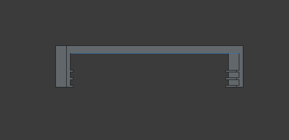
I would use the same clip-on mounting concept, using the cooling fins on the sides. But with only one viewing angle, a flat cross-piece would support the body of the radio to keep it more secure. If I designed the legs carefully, they would be rigid enough to support the radio, and I could make sure the feet were angled just so to ensure they would sit flat on the surface.
When I did the mic hook design, I actually saved a separate file containing just the bracket that clipped onto the cooling fins across the back of the radio, just in case I wanted to design some other accessory that would attach in the same way. I did not envision that accessory being some kind of stand, and I never contemplated clipping it across the underside of the radio. Is the G90 even symmetrical in that way? A quick test fit of the mic hook on the underside of the radio showed me that it is, and that made the design much simpler.
Design
The initial design was pretty simple. I did not even bother doing any pencil-and-paper planning. I just made a fresh copy of the standalone bracket and went to work. Because I had parameterized it with dimensions specified in a Spreadsheet in FreeCAD, it was easy to modify. For example, I wanted to make it wider, so I just changed the value in the spreadsheet.
I also designed the original piece using a reflection, which is to say I designed half of it and then FreeCAD simply mirrored it to create an exactly symmetrical other half. So to design this part, I set the “tip” in FreeCAD, which indicates where in the timeline you’re working, to the last change before the reflection. Then I only had to design a single leg, and after setting the “tip” back to the end, the other leg was generated automatically.
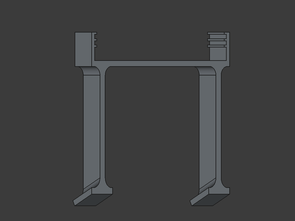
To determine the height, I just eyeballed it … I lifted the front of the radio up to the angle I wanted and simply measured how far up that was. I sketched the shape of the leg and padded it to that height (using a parameter, of course).
I then added a little square foot at the bottom, and offset the leg from the outside (again using a parameter for easy adjustment) so that the edge of the foot would be even with the edge of the bracket.
The only tricky bit (and it was not very tricky), was angling the foot so that it would sit flat. Knowing the radio formed the hypotenuse of a right triangle, and knowing the dimensions of the sides, I knew it was possible to calculate the angle of the radio with respect to the surface, but it’s been a long time since I did that kind of trigonometry so I just found an online calculator and plugged it in. And of course, I made the angle a parameter in case I wanted to adjust it later.
I added some filets to some of the corners, partly for aesthetic reasons and partly because I thought it might make it a bit sturdier. After that, I felt ready to start printing!
Test Prints
If you’ve read my other posts on printing, you know by now that I’m a big fan of test prints to save time and material while working out the bugs. Unfortunately I already threw away the test pieces so I can’t show a picture.
I started by printing just one side of the clip and the foot so that I could try to gauge the fit and the angle of the foot. I immediately noticed that there was quite a bit of play where the clip engaged the cooling fins. I had not noticed it before but re-checking the speaker redirector and mic hook, I found they had some play as well. But for a part that sat on top of the radio and did not support any significant weight, it was not noticeable. Well, on a part that had to support the weight of the radio at a somewhat precise angle, that wiggle was very noticeable.
So, I spent some time tweaking the size of the teeth on the clip. As you might have already guessed, those dimensions were also parameterized already so I just had to experiment with changing values in the Spreadsheet and then printing small tests until I found the size that gave steady fit. The cooling fins are tough to measure with my calipers. I could never get a great measurement so I had to resort to trial and error.
Full Print
Once I got the fit of the teeth dialed in, I printed the whole thing and snapped it on the radio. The angle on the feet was not quite perfect, but it was pretty close. I also had some rubber stick-on pads lying around that are a bit rounded. Putting those on gave it a nice grip on the tabletop and corrected for whatever slop there was in the angles. I was just about ready to pat myself on the back and throw it in the backpack with my radio to try out once the weather improved.
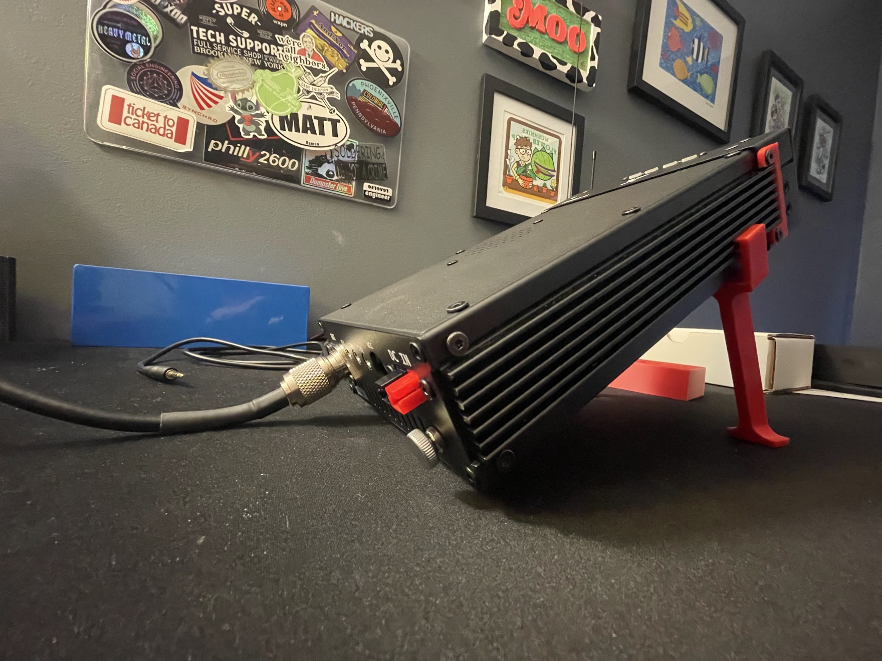
But then something caught my eye. The bottom of the coax connector was VERY close to the table. I probably should have designed this thing with all the wires plugged into the back! Sure enough, when I attached the coax I found that the connector did clear the table, but the radio was fully resting on the coax just past the connector. That did not seem great for either the connector or the cable itself. It also pushed the radio off-kilter which torqued the stand and made the whole thing unstable.
Back To The Drawing Board
This was going to need to be redesigned a bit. Lowering the angle was one possibility but I found it would have to be so low that it was only marginally better than the stand I had been using before. What I needed was a way to elevate the back of the radio a bit. After pondering this for a bit I realized the answer was right in front of me - there could be a second, shorter set of legs for the rear of the radio!
Thanks once again to the habit my friend taught me from day one of parameterizing things as much as possible, this was super easy - I needed only to figure out what height I wanted the back to be, make a copy of the front legs and tweak that dimension accordingly. I printed just one leg/bracket to test it out and the coax was no longer supporting the weight of the radio.
The only other thing I had to do was change the angles of the feet since elevating the back effectively lowered the angle a bit. To do this I decided to just print the full back legs and then measure from the front of the radio, the back, and through to the table. Unfortunately I could not find my tape measure at the time, or anything else suitable to measure my new hypotenuse length that extended longer than the radio itself. I thought I was going to have to give up until I could find (or replace?) the tape measure before I remembered that the iPhone has a built-in level feature that will even tell you the angle! I simply put the feet on the radio, rested the phone on the back and read the angle that way. My 3D printing guru friend later told me that another option could be to mock up the shape of the radio in FreeCAD and then I could measure the angle in the software. Something to consider for later, but the iPhone got the job done.
If you remember from earlier that I had even made the angle of the feet a parameter, all I had to do was tweak that angle and I would be good to go. It was doing this that I realized why the angle of the legs didn’t seem quite correct in the initial print - when doing the mental math of the complementary angles, I must have forgotten to carry a one; the original angle was off by 10 degrees! Oops! I adjusted the feet to the new angle, double-checked they were correct, and sent them to the printer.
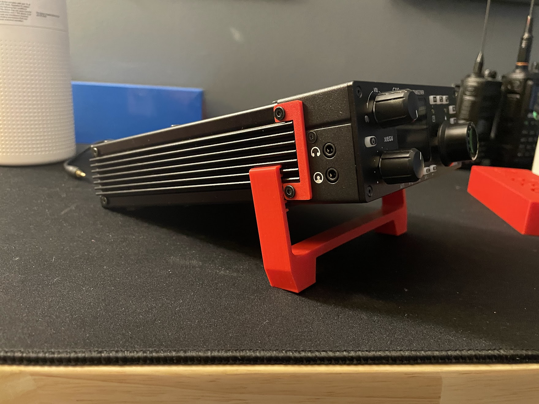
Great Scott!
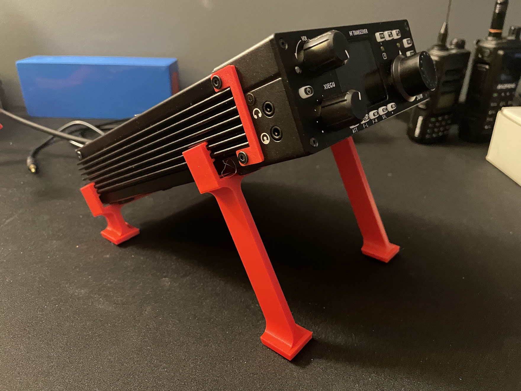
It worked! The new sets of legs are easy to put on and take off, they hold the radio securely, raise the screen to a great viewing angle, and avoid stressing the wires and connectors on the back of the radio, and they are still compact enough to stow in the backpack with all my other radio stuff.
Print Your Own
Do you want to print your own? I have shared it on Printables. Feel free to give it a go!
Post Script
Just days after I finalized this design, my 3D printing friend mentioned that he wanted to sell one of his older printers to make room for a better one to support his business. For the past few years I would not have considered it, not even for the bargain basement price he offered. But ham radio rekindled my love of 3D printing to the point where I could not resist. So now, instead of my barebones Ender 3, I’ve got a modern Prusa MK4S with all the modern conveniences - automatic bed leveling, filament sensors, and it prints literally 3x faster. My friend even included the MMU3 multi-material add-on which he had never actually set up. It took me awhile to get that going (before I could assemble and install it, I had to 3D print most of the plastic parts (in PETG, which I had never used before), and then I had to modify the cabinet that the printer sits on to accommodate all the spools), but now I have the ability to print up to five colors in one go.
I’m looking forward to my next design inspiration.